
For several years, a fully-automated plastic drinking cup production line used excessive amounts of raw materials (plastic PET pellets) due to a wide distribution in the weight of the formed cups. When process operators and engineers had tried to reduce the plastic pellet usage by reducing the average formed cup weight, many cups – because of the wide variation – fell below the customer-specified minimum weight. The process thus had to be reset to a higher weight target in order to avoid those out-of-specification cups. A previous process improvement team attempted to find the sources of variation through some data collection and a couple of two-factor/two-level full-factorial experiments. They were unsuccessful, however, as the factors used in the experiments did not explain the response variation.
The Problem
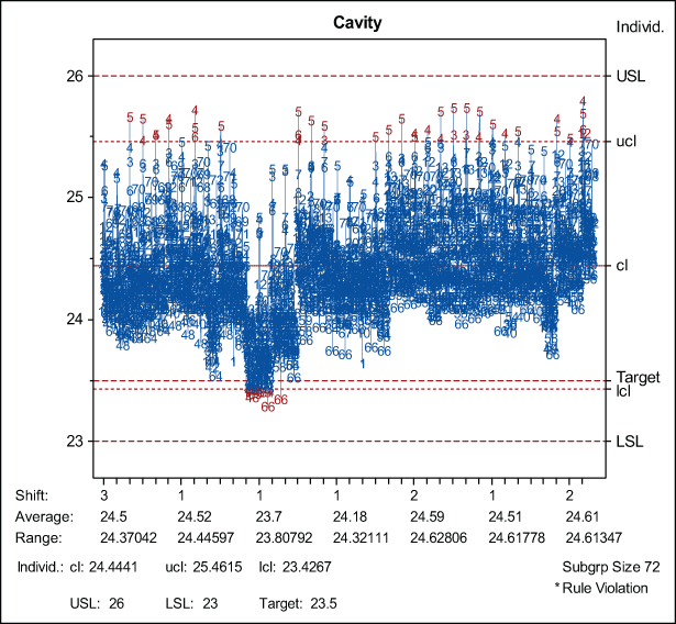
The automated cup line has an average cup weight of 24.5 grams, which is 1 gram higher than the target of 23 grams (also the lower specification limit [LSL]) for an individual cup’s weight. To avoid low-weight cup failures, the operators usually raise the target cup weight average, increasing the amount of resin use. An additional 260,198 pounds of resin is used annually with a cost of poor quality (COPQ) of $195,148. Figure 1 shows the current output of cup weights over 30 days (3 shifts per day).
Solving the Problem with DMAIC (Define, Measure, Analyze, Improve, Control)
A Six Sigma project team (comprised of machine operators, quality assurance personnel, maintenance staff and other factory subject-matter experts) was created to reduce weight distribution variability to achieve a minimum Cp of 1.22. The team aimed to improve the production process such that the cup weight average could be retargeted closer to the 23-gram LSL, saving 0.5 grams of resin on average per cup produced. If such an improvement were achieved, the team could reduce by 50 percent the use of the additional resin – a savings of $97,750 per year.
As part of the Define phase, a SIPOC (suppliers, input, process, output, customers) map was created (Figure 2).
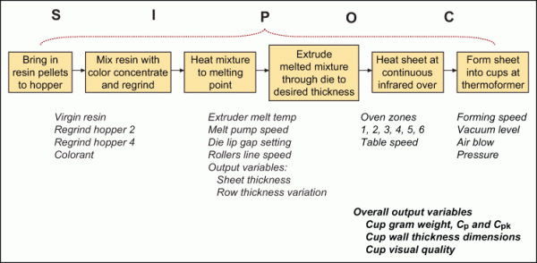
The process includes these pieces of equipment:
- A plastic-pellet extruder fed with virgin PET resin pellets, colorant and regrinds (scraped plastic cups that are reground and fed back into the process). The extruder mixes all of them and supplies a constant plastic paste.
- A chilled stainless steel hard-chromed roller system that creates a wide plastic sheet.
- A beta-ray scanner that continuously monitors the thickness of the plastic sheet and also provides a closed-loop control to the extruder and roller system.
- A wide, flat infrared oven that reheats the plastic sheet to specific target temperature.
- A 72-cavity thermoforming mold that receives the heated plastic sheet and stamps out 72 cups at each press stroke (also known as a mold shot).
- A 72-position puncher that cuts the cups from the formed plastic sheet (called webbing) that presents the separated cups in stacks to a conveyor system.
- An automatic box filler that takes the stacks of cups from the conveyor and fills up boxes with stacks of 20 cups.
During the early brainstorming sessions of the project team, changes such as mold temperature increases and mold cavity (plug assist) replacements were suggested – and implemented – but cup-weight distribution remained the same. The team decided to get back to basics, and a multivary study was initiated.
Multivary Studies
Multivary studies make no changes to the process being studied; they do, however, require the use of detailed process and product data in order to distinguish, by categories, the source or sources of variation. Graphical tools, multivary studies help identify the where or when of the biggest source of variation. The variation categories can be grouped as: time to time, lot to lot, piece to piece, within piece, shift to shift, operator to operator, etc.
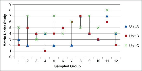
Data collection is designed to include all the suspected sources of variation, graphed against the output variable Y. The graph below shown in Figure 3 is an example of a multivary study with group-to-group, A, B or C, variation.
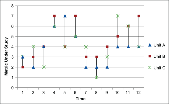
In Figure 4, below, there is a time-related cyclical variation, represented by the changes between 1, 2 and 3 groups to 4, 5 and 6, and so on.
In the example of the plastic cups, the analysis of the sampled data showed that high variation was always present with no correlation to time-related categories. Next, the team looked toward positional variation, a particular type of multivary study.
Looking at Each Molded Cup
Each molded cup comes from a thermoforming mold with 72 cavity locations. Figure 5 shows a diagram of the mold, with each cavity position numbered and the sides and direction of travel indicated.
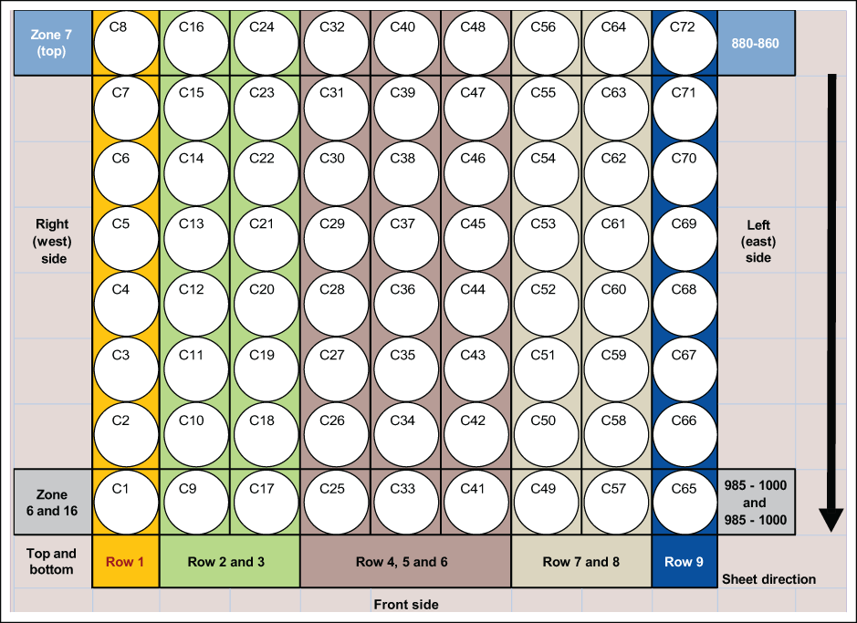
Data was collected from cup units coming from each cavity as shown in Figure 6. The team was thus able to identify all of the cavities that fell below the minimum limit at every sampled mold shot (every 72 units coming from a single mold stroke).
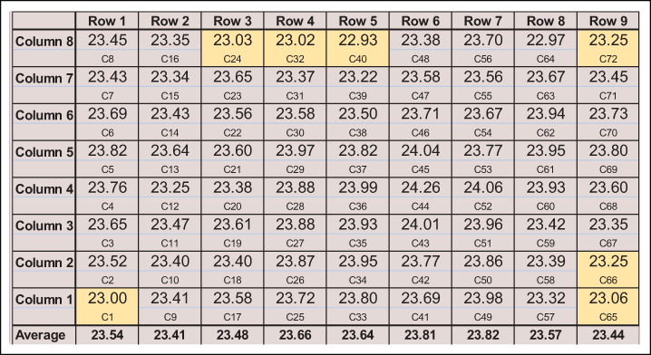
After a few samples, it was clear that the cavity position inside the mold was the highest source of variation, with product that come from one side of the mold running consistently below the average shot.
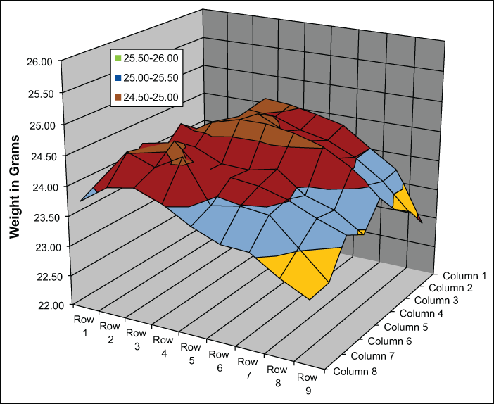
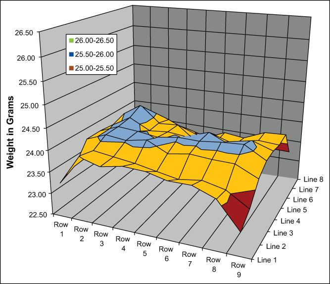
By creating a surface map using the average weights produced in each individual cavity, the row-to-row differences across the mold were clear. As displayed in Figure 7, rows 1 through 4 have higher average weights than rows 7 through 9.
Looking at Sheet Thickness Distribution
The project team began to look for clues as to why the side-to-side weight variation was occurring by returning to the SIPOC exercise. An important input variable to the formed cup weight was the extruded sheet thickness. Fortunately, a beta-ray scanner was available to monitor the thickness in a continuous raster (line-by-line) scan and provided reliable numbers. The team was able to compare plastic sheet thickness to cup weight and found no correlation – the extruded plastic sheet had a consistent thickness distribution among the width axes while the formed cup still displayed a side-to-side difference.
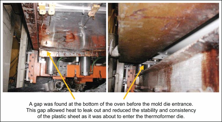
Team members were left to examine the infrared oven and the mold itself. Previous work included looking at the thermoforming electrical heaters and thermocouples, but they had shown no critical issue. This time, the team decided to disassemble and inspect the infrared oven entirely, looking for any clues as to the uneven weight distribution.
Upon inspecting the electrical components, team members found nothing wrong. The physical review, however, found that a section of the oven had a gap between the oven and the mold interface, which allowed heat to escape.
After this physical gap was fixed and several full mold shot samples were run, a more even weight distribution was seen across the mold. As shown in Figure 9, the variance in weights narrowed after the infrared oven was repaired.
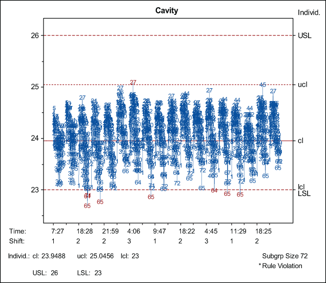
Issues with Position 65
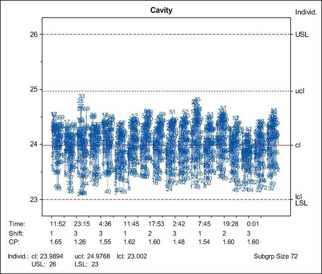
A particular mold cavity, position 65, often had a low cup weight (Figure 10). The mold was inspected, cleaned and the incumbent cavity fixture replaced. Unfortunately, the low weight behavior persisted. The team revisited the cavity location and found a vacuum line had clogged; they fixed it by flushing the lines out. This last action allowed the team to eliminate cavity 65 as a recurring low weight cup (Figure 11).
After this step, all special variations had been elminiated. The project team shifted its focus to reducing common cause variation, returning again to its SIPOC map to identify critical inputs to process variation. Data analysis showed that oven settings and initial sheet thickness contributed to cup-weight variation.
A standard three-factor full-factorial design of experiments (DOE) was set up with the factors of oven temperature, plastic sheet thickness and plastic pellet regrind. The experiment data analysis resulted in a good R2 square of 97.87 percent with sheet thickness and regrind set point as strong contributors to the overall variation.
Further DOE work focused on fixing the oven temperatures, and working with sheet thickness and regrind levels allowed the team to establish optimal input control parameters. The average weight was reduced to the 24-gram target with none (or very few) cups going under the 23-gram LSL. The original project goal of reducing raw material usage was achieved with a savings of $100,000. Accordingly, the process Cp was increased to greater than the targeted minimum of 1.5.
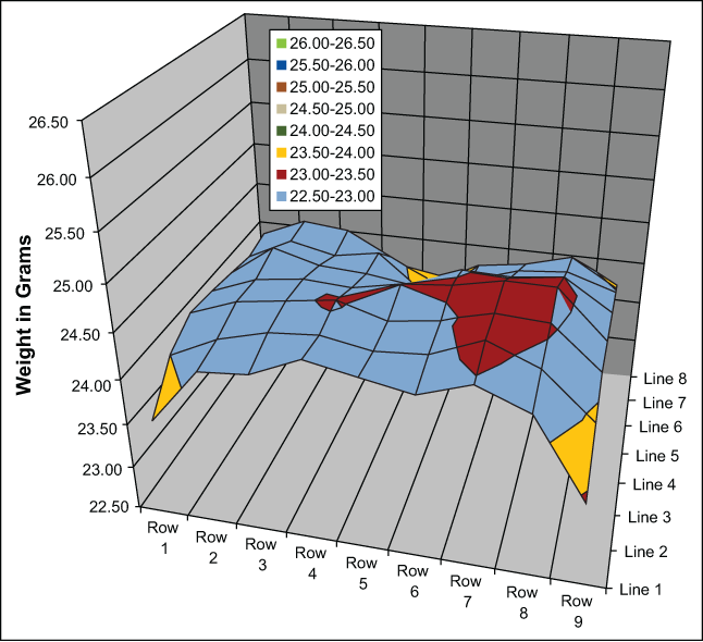
Today cup-weight surface mapping is more even across the mold with a tighter distribution. The low points, located at the front corners (Figure 12), cannot be improved without redesigning the mold and reducing the size of the mold from 72 to 60 cavities. This change was considered, but it would have resulted in a-14 percent reduction in productivity; it was not pursued.
Conclusion
This process improvement project demonstrates that it is important to not use sophisticated statistical tools (such as DOE) to analyze a process before reducing the special input variables present in the process in question. Otherwise, time, energy and resources may be wasted without ever finding the critical characteristics to enable the control and improvement of a process.